Beams Fixed at Both Ends with Continuous and Point Loads: Load & Deflection Formulas
Stress, deflections and supporting loads.
- Beams - Supported at Both Ends - Continuous and Point Loads
- Beams - Fixed at One End and Supported at the Other - Continuous and Point Loads
- Beams - Fixed at Both Ends - Continuous and Point Loads
Beam Fixed at Both Ends - Single Point Load
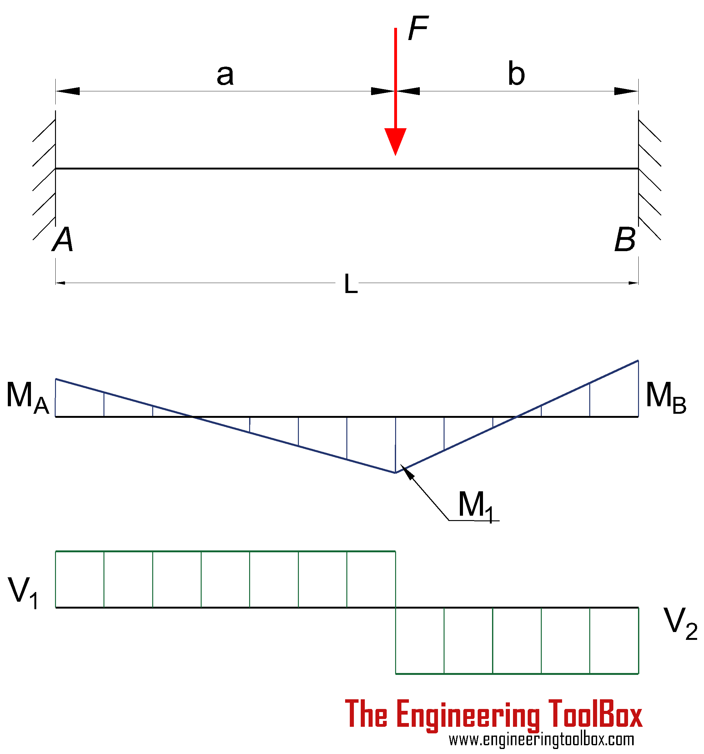 Bending Moment
MA = - F a b2 / L2 (1a)
where
MA = moment at the fixed end A (Nm, lbf ft)
F = load (N, lbf)
MB = - F a2 b / L2 (1b)
where
MB = moment at the fixed end B (Nm, lbf ft)
MF = 2 F a2 b2 / L3 (1c)
where
MF = moment at the point load (Nm, lbf ft)
Deflection
δF = F a3 b3 / (3 L3 E I) (1d)
where
δF = deflection at point load (m, ft)
E = Modulus of Elasticity (Pa (N/m2), N/mm2, psi)
I = Area Moment of Inertia (m4, mm4, in4)
Support Reactions
RA = F (3 a + b) b2 / L3 (1f)
where
RA = support force at fixed end A (N, lbf)
RB = F (a + 3 b) a2/ L3 (1g)
where
RB = support force at fixed end B (N, lbf)
Beam Fixed at Both Ends - Uniform Continuous Distributed Load
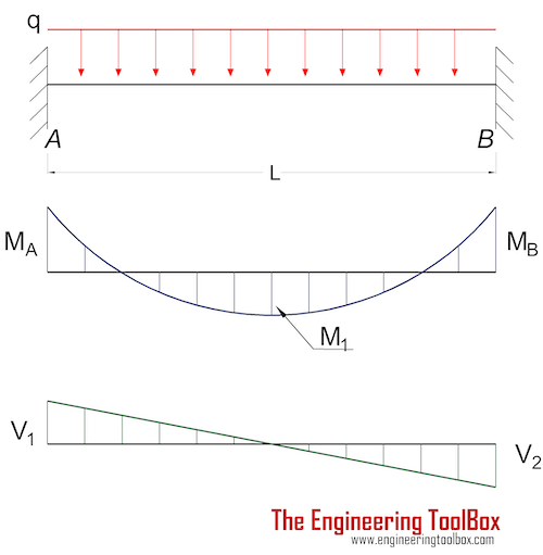 Bending Moment
MA = MB
= - q L2 / 12 (2a)
where
M = moments at the fixed ends (Nm, lbf ft)
q = uniform load (N/m, lbf/ft)
M1 = q L2 / 24 (2b)
where
M1 = moment at the center (Nm, lbf ft)
Deflection
δmax = q L4 / (384 E I) (2c)
where
δmax = max deflection at center (m, ft)
E = Modulus of Elasticity (Pa (N/m2), N/mm2, psi)
I = Area Moment of Inertia (m4, mm4, in4)
Support Reactions
RA = RB
= q L / 2 (2d)
where
R = support forces at the fixed ends (N, lbf)
Beam Fixed at Both Ends - Uniform Declining Distributed Load
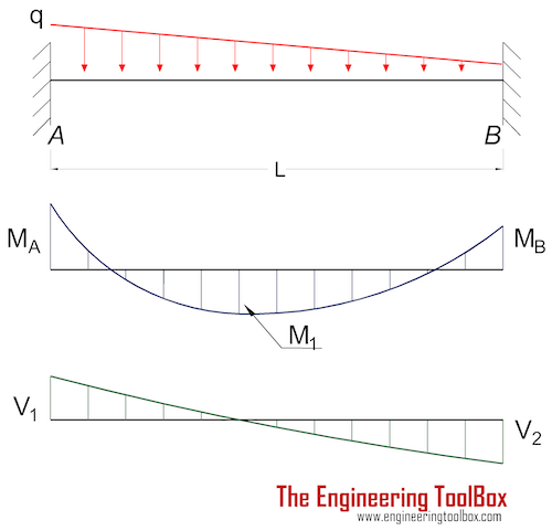 Bending Moment
MA = - q L2 / 20 (3a)
where
MA = moments at the fixed end A (Nm, lbf ft)
q = uniform declining load (N/m, lbf/ft)
MB = - q L2 / 30 (3b)
where
MB = moments at the fixed end B (Nm, lbf ft)
M1 = q L2 / 46.6 (3c)
where
M1 = moment at x = 0.475 L (Nm, lbf ft)
Deflection
δmax = q L4 / (764 E I) (3d)
where
δmax = max deflection at x = 0.475 L (m, ft)
E = Modulus of Elasticity (Pa (N/m2), N/mm2, psi)
I = Area Moment of Inertia (m4, mm4, in4)
δ1/2 = q L4 / (768 E I) (3e)
where
δ1/2 = deflection at x = 0.5 L (m, ft)
Support Reactions
RA = 7 q L / 20 (3f)
where
RA = support force at the fixed end A (N, lbf)
RB = 3 q L / 20 (3g)
where
RB = support force at the fixed end B (N, lbf)
Beam Fixed at Both Ends - Partly Uniform Continuous Distributed Load
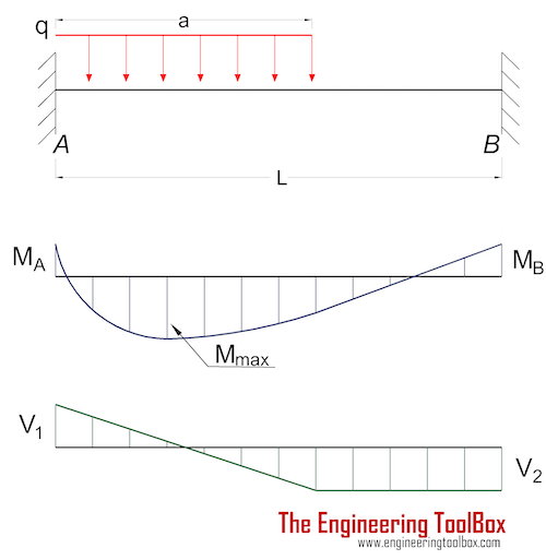 Bending Moment
MA = - (q a2 / 6) (3 - 4 a / l + 1.5 (a / L)2) (4a)
where
MA = moment at the fixed end A (Nm, lbf ft)
q = partly uniform load (N/m, lbf/ft)
MB = - (q a2 / 3) (a / L - 0.75 (a / L)2) (4b)
where
MB = moment at the fixed end B (Nm, lbf ft)
Support Reactions
RA = q a (L - 0.5 a) / L - (MA - MB ) / L (4c)
where
RA = support force at the fixed end A (N, lbf)
RB = q a2 / (2 L) + (MA - MB ) / L (4d)
where
RB = support force at the fixed end B (N, lbf)
Insert beams to your Sketchup model with the Engineering ToolBox Sketchup Extension
