Engineering ToolBox - Resources, Tools and Basic Information for Engineering and Design of Technical Applications!

Beams - Fixed at One End and Supported at the Other - Continuous and Point Loads

Supporting loads, moments and deflections.

Sponsored Links

Beam Fixed at One End and Supported at the Other - Single Point Load

Beam fixed at one end and supported at the other - single point loadBending Moment

MA = - F a b (L + b) / (2 L2)                               (1a)

where

MA = moment at the fixed end (Nm, lbf ft)

F = load (N, lbf)

MF = Rb b                               (1b)

where

MF = moment at point of load F (Nm, lbf ft)

Rb = support load at support B (N, lbf)

Deflection

δF = F a3 b2 (3 L + b) / (12 L3 E I)                                  (1c)

where

δF = deflection (m, ft)

E = Modulus of Elasticity (Pa (N/m2), N/mm2, psi)

I = Area Moment of Inertia (m4, mm4, in4)

Support Reactions

RA = F b (3 L2 - b2) / (2 L3)                                 (1d)

where

RA = support force in A (N, lbf)

RB = F a2 (b + 2 L ) / (2 L3)                                 (1f)

where

RB = support force in B  (N, lbf)

Beam Fixed at One End and Supported at the Other - Continuous Load
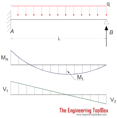
Beam fixed at one end and supported at the other - continous loadBending Moment

MA = - q L2 / 8                               (2a)

where

MA = moment at the fixed end (Nm, lbf ft)

q = continuous load (N/m, lbf/ft)

M1 = 9 q L2 / 128                              (2b)

where

M1 = maximum moment at x = 0.625 L  (Nm, lbf ft)

Deflection

δmax = q L4 / (185 E I)                                  (2c)

where

δmax = max deflection at x = 0.579 L (m, ft)

δ1/2 = q L4 / (192 E I)                                  (2d)

where

δ1/2 = deflection at x = L / 2   (m, ft)

Support Reactions

RA = 5 q L / 8                            (2e)

RB = 3 q L / 8                            (2f)

Beam Fixed at One End and Supported at the Other - Continuous Declining Load
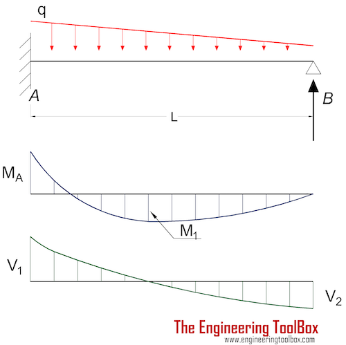
Beam fixed at one end and supported at the other - continous declining loadBending Moment

MA = - q L2 / 15                               (3a)

where

MA = moment at the fixed end (Nm, lbf ft)

q = continuous declining load (N/m, lbf/ft)

M1 = q L2 / 33.6                              (3b)

where

M1 = maximum moment at x = 0.553 L (Nm, lbf ft)

Deflection

δmax = q L4 / (419 E I)                                  (3c)

where

δmax = max deflection at x = 0.553 L   (m, ft)

δ1/2 = q L4 / (427 E I)                                  (3d)

where

δ1/2 = deflection at x = L / 2   (m, ft)

Support Reactions

RA = 2 q L / 5                            (3e)

RB = q L / 10                            (3f)

Beam Fixed at One End and Supported at the Other - Moment at Supported End
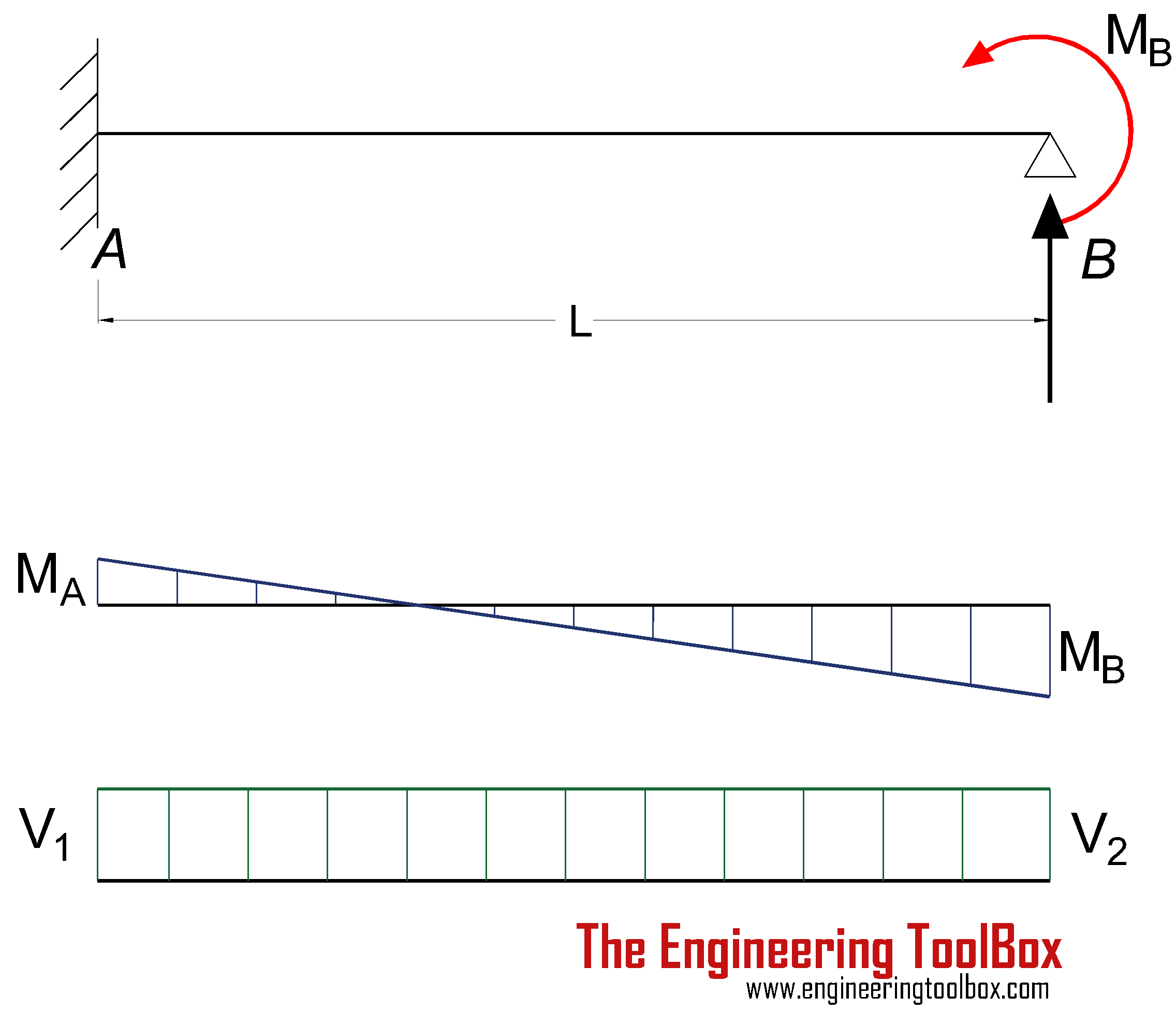
Beam fixed at one end and supported at the other - moment at the supported endBending Moment

MA = -MB / 2                               (4a)

where

MA = moment at the fixed end (Nm, lbf ft)

Deflection

δmax = MB L2 / (27 E I)                                  (4b)

where

δmax = max deflection at x = 2/3 L   (m, ft)

Support Reactions

RA = 3 MB / (2 L)                            (4c)

RB = - 3 MB / (2 L)                       (4d)

Sponsored Links

Related Topics

Related Documents

Sponsored Links

Engineering ToolBox - SketchUp Extension - Online 3D modeling!

3D Engineering ToolBox Extension to SketchUp - add parametric components to your SketchUp model

Add standard and customized parametric components - like flange beams, lumbers, piping, stairs and more - to your Sketchup model with the Engineering ToolBox - SketchUp Extension - enabled for use with the amazing, fun and free SketchUp Make and SketchUp Pro .Add the Engineering ToolBox extension to your SketchUp from the SketchUp Pro Sketchup Extension Warehouse!

Translate
About the Engineering ToolBox!

Privacy

We don't collect information from our users. Only emails and answers are saved in our archive. Cookies are only used in the browser to improve user experience.

Some of our calculators and applications let you save application data to your local computer. These applications will - due to browser restrictions - send data between your browser and our server. We don't save this data.

Google use cookies for serving our ads and handling visitor statistics. Please read Google Privacy & Terms for more information about how you can control adserving and the information collected.

AddThis use cookies for handling links to social media. Please read AddThis Privacy for more information.

Citation

This page can be cited as

  • Engineering ToolBox, (2003). Beams - Fixed at One End and Supported at the Other - Continuous and Point Loads . [online] Available at: https://www.engineeringtoolbox.com/beams-fixed-end-d_560.html [Accessed Day Mo. Year].

Modify access date.

. .

close

3D Engineering ToolBox - draw and model technical applications! 2D Engineering ToolBox - create and share online diagram drawing templates! Engineering ToolBox Apps - mobile online and offline engineering applications!

Scientific Online Calculator

Scientific Calculator

3 10

Sponsored Links
.