Bernoulli Equation
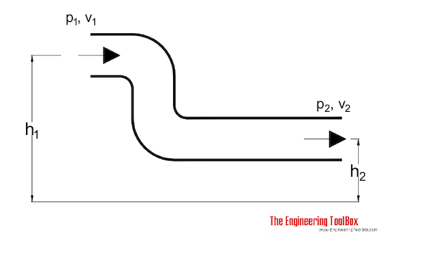
Conservation of energy in a non-viscous, incompressible fluid at steady flow.
The statement of conservation of energy is useful when solving problems involving fluids. For a non-viscous, in-compressible fluid in a steady flow, the sum of pressure, potential and kinetic energies per unit volume is constant at any point.
Bernoulli's principle: At points along a horizontal streamline, higher pressure regions have lower fluid speed and lower pressure regions have higher fluid speed.
A special form of the Euler’s equation derived along a fluid flow streamline is often called the Bernoulli Equation:

Energy Form
For steady state in-compressible flow the Euler equation becomes
E = p1 / ρ + v12 / 2 + g h1
= p2 / ρ + v2 2 / 2 + g h2 - Eloss
= constant (1)
where
E = energy per unit mass in flow (J/kg, Btu/slug)
p = pressure in the fluid (Pa, psf)
ρ = density of fluid (kg/m3, slug/ft3)
v = velocity of fluid (m/s, ft/s)
Eloss = energy loss per unit mass in flow (J/kg, Btu/slug)
1 psi = 144 psf
Head Form
(1) can be modified by dividing with gravity like
h = p1 / γ + v12 / (2 g) + h1 = p2 / γ + v2 2 / (2 g) + h2 - Eloss / g
= constant (2)
where
h = head (m fluid column, ft fluid column)
γ = ρ g = specific weight of fluid (N/m3, lbf/ft3)
Equation (2) is often referred to as the "head" because all elements has the unit of length.
Note! - the head unit is with reference to the density of the flowing fluid. For other units - like mm Water Column - check Velocity Pressure Head.
Dynamic Pressure
(1) and (2) are two forms of the Bernoulli Equation for a steady state in-compressible flow. If we assume that the gravitational body force is negligible - the elevation is small - then the Bernoulli equation can be modified to
p = p1 + ρ v12 / 2
= p2+ ρ v22 / 2 - ploss
= p1 + pd1
= p2 + pd2 - ploss (3)
where
p = pressure (Pa, psi)
ploss = pressure loss (Pa, psi)
pd = 1/2 ρ v2= dynamic pressure (Pa, psf)
It is common to refer to the flow velocity component as the dynamic pressure of the fluid flow.
Note! - increased flow velocity reduces pressure - decreased flow velocity increases pressure.
This phenomena can be observed in a venturi meter where the pressure is reduced in the constriction area and regained after. It can also be observed in a pitot tube where the stagnation pressure is measured. The stagnation pressure is where the velocity component is zero.
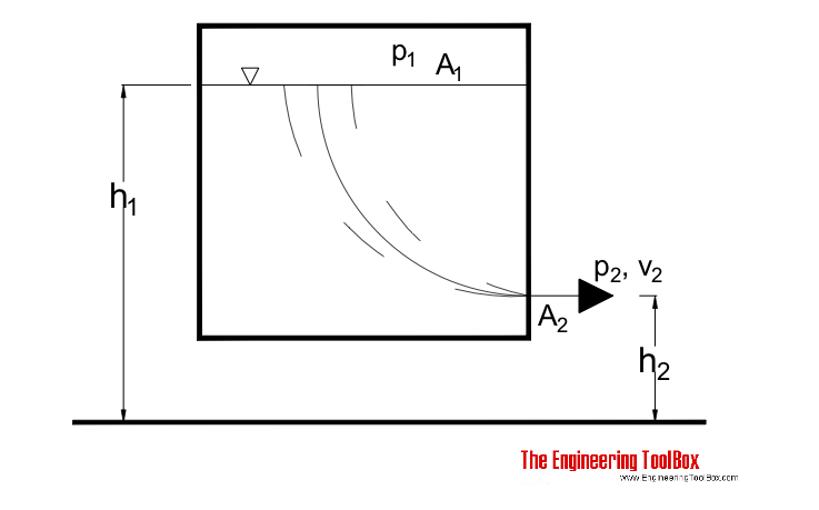
Discharge from a Pressure Vessel - Bernoulli Equation and Flow from a Tank through a small Orifice
Liquid flows from a tank through a orifice close to the bottom. The Bernoulli equation can be adapted to a streamline from the surface (1) to the orifice (2) :

p1 / γ + v12 / (2 g) + h1
= p2 / γ + v2 2 / (2 g) + h2 - Eloss / g (4)
By multiplying with g and assuming that the energy loss is neglect-able - (4) can be transformed to
p1 / ρ + v12 / 2 + g h1
= p2 / ρ + v2 2 / 2 + g h2 (4b)
Discharge Velocity
If
h = h1 - h2 (4c)
and (according the continuity equation)
v1 = (A2 / A1) v2 (4d)
then the velocity out of the orifice can be expressed as
v2 = ((2 / (1 - A2 2 / A12)) (g h + (p1 - p2) / ρ))1/2 (5)
Vented Tank
For a vented tank where the inside pressure equals the outside pressure
p1 = p2 (5b)
and the surface area is much larger than the orifice area
A1 >> A2 (5c)
- then eq. 5 can be modified to
v2 = (2 g h)1/2 (6)
"The velocity out from the tank is equal to speed of a freely body falling the distance h ." - also known as Torricelli's Theorem.
Example - outlet velocity from a vented tank
The outlet velocity from a tank with level 10 m can be calculated as
v2= (2 (9.81 m/s2) (10 m))1/2
= 14 m/s
Orifice Discharge Coefficient
Eq. 6 is for ideal flow without pressure loss in the orifice. In the real worls - with pressure loss - eq. 6 can be expressed with a coefficient of discharge - friction coefficient - as
v2 = c (2 g h)1/2 (6b)
where
c = coefficient of discharge
The coefficient of discharge can be determined experimentally. For a sharp edged opening it may bee as low as 0.6. For smooth orifices it may bee between 0.95 and 1 .
Pressurized Tank
If the tank is closed, pressurized and the level between the surface and the discharge outlet minimal (the influence from level difference is very small compared to pressure influence in eq. 5) - the discharge velocity can be expressed as
v2 = c (2 (p1 - p2) / ρ)1/2 (7)
Example - Outlet Velocity from a Pressurized Tank
The outlet velocity of a pressurized tank where
p1 = 0.2 (MN/m2, 106 Pa)
p2= 0.1 (MN/m2, 106 Pa)
A2 / A1 = 0.01
h = 10 (m)
can be calculated as
V2= ( (2 / (1 - (0.01)2) ((0.2×10⁶ N/m2) - (0.1×10⁶ N/m2)) / (1000 kg/m3) + (9.81 m/s2) (10 m)))1/2
= 19.9 m/s
Energy Loss through a Reduction Valve
When fluid flows through a reduction valve and the pressure is reduced - there is an energy loss. By neglecting the change in elevation (h1 = h2) and the change in fluid velocity (v1 = v2) the pressure energy before the valve and the pressure energy after the valve including the energy loss through the valve - is constant. The Bernouilli equation can be modified to
p1 / ρ = p2 / ρ + Eloss (8)
where
Eloss = energy loss through valve (J)
(8) can be transformed to:
Eloss = ( p1 - p2) / ρ (8b)


