Sluice Gate - Volume Flow Measurements
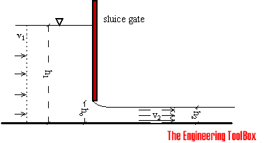
Sluice gates can be used to control and measure volume flow rates in open channels and rivers, mainly in connection to hydro power plants.
Sluice gate flow metering is often used to measure flow rate in open channels. Sluice gates are also often used to modulate flow.

The sluice gate flow rate measurement is based on the Bernoulli Equation and can be expressed as:
1/2 ρ v12 + ρ g h1 = 1/2 ρ v22 + ρ g h2 (1)
where
h = elevation height (m)
ρ = density (kg/m3)
v = flow velocity (m/s)
The pressure components in the equation are in general irrelevant since pressure upstream and downstream are the same (p1 - p2 = 0).
Assuming uniform upstream and downstream velocity profiles - the Continuity Equation gives:
q = v1 A1
= v2 A2 (2)
where
q = flow rate (m3/s)
A = flow area (m2)
(2) can be modified to:
q = v1 h1 b
= v2 h2 b (3)
where
b = width of the sluice (m)
h1 = upstream height (m)
h2 = downstream height (m)
Combining (1) and (3), gives the "ideal" equation:
q = h2 b (2 g (h1 - h2) /(1 -(h2 / h1)))1/2 (4)
Assuming h1 >> h2 (4) can be modified to:
q = h2 b (2 g h1)1/2 (5)
This is approximately true when the depth ratio h1/ h2 is large, the kinetic energy upstream is negligible (v1 is small) and the fluid velocity after it has fallen the distance (h2 - h1) ≈ h1 - is:
v2 = (2 g h1)1/2 (6)
The ideal equation (3) can be modified with a discharge coefficient:
q = cd h0 b (2 g h1)1/2 (7)
where
cd = discharge coefficient
The discharge coefficient depends on different parameters - such as upstream and tail-water depths, gate opening, contraction coefficient of the gate and the flow condition.
In practice the typical discharge coefficient is approximately 0.61 for free flow conditions and depth ratios ho/ h1 < 0.2.
Sluice Gate Specifications
The most commonly used specification for sluice gates in water and wastewater treatment plants is ANSI/AWWA C560-00. This specification should be used as a guidance for gates selection and operating equipment and associated hardware.
Example - Flow Rate through a Sluice Gate
Water flows under a sluice gate with an opening height of 0.4 m. The width of the sluice is 3 m and the height from the water surface to the bottom of the sluice is 10 m.
Since h1 >> h2 and the depth ratio 0.4/10 < 0,2 - the contraction coefficient can be set to 0.61 - and equation (7) can be used for flow calculation:
q = 0.61 (0.4 m) (3 m) (2 (9.81 m/s2) (10 m))1/2
= 10.25 m3/s


