Fluid Flowmeters - Comparing Types
An introduction to the different types of fluid flowmeters - Orifices, Venturies, Nozzles, Rotameters, Pitot Tubes, Calorimetrics, Turbine, Vortex, Electromagnetic, Doppler, Ultrasonic, Thermal, Coriolis.
Flow is classified into open channel flow and closed conduit flow.
Open channel flow occur when the flowing stream has a free or unconstrained surface open to the atmosphere. Flows in canals or vented pipelines - like drain and sewers - which are not flowing full, are typical examples.
In open channel flow the force causing the flow the force of gravity on the fluid. A progressive fall or decrease in the water surface elevation occurs as the flow moves downstream.
Closed conduit flow occurs when the flow is caused by a pressure difference in the conduit. Flow in water supply pipes or district heating pipes are typical examples. The flow rate depends mainly on the pressure difference between the ends, the distance between the ends, the area of the conduit and the hydraulic properties of the conduit - like the shape, roughness and restrictions like bends.
Flow Metering Principals
- Differential Pressure Flow meters
- Velocity Flow meters
- Positive Displacement Flow meters
- Mass Flow meters
- For Open Channel Flow meters - weirs, flumes, submerged orifices, current meters, acoustic flow meters and more
Differential Pressure Flow Meters
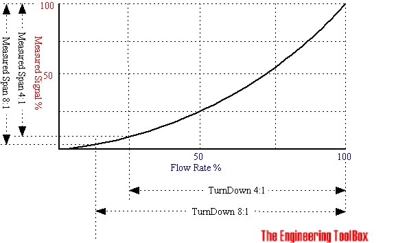
In a differential pressure drop device the flow is calculated by measuring the pressure drop over an obstructions inserted in the flow. The differential pressure flow meter is based on the Bernoulli Equation where the pressure drop and the further measured signal is a function of the square flow speed.
dp = ρ v2 / 2 (1)
where
dp = pressure difference (Pa, psi)
ρ = density of fluid (kg/m3, slugs/ft3)
v = flow velocity (m/s, in/s)
Note that it is common to use "head" instead of "pressure"
h = dp / γ (2)
where
h = head (m, in)
γ = specific weight (N/m3, lb/ft3)
Common types of differential pressure flow meters are:
Orifice Plate
With an orifice plate, the fluid flow is measured through the difference in pressure from the upstream side to the downstream side of a partially obstructed pipe. The plate obstructing the flow offers a precisely measured obstruction that narrows the pipe and forces the flowing fluid to constrict.
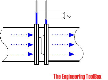
The orifice plates are simple, cheap and can be delivered for almost any application and in any material.
The Turn Down Ratio for orifice plates are less than 5:1. Their accuracy are poor at low flow rates. A high accuracy depend on an orifice plate in good shape, with a sharp edge to the upstream side. Wear will reduce the accuracy.
Venturi Tube
Due to simplicity and dependability, the Venturi tube flowmeter is often used in applications where it's necessary with higher Turn Down Ratios, or lower pressure drops, than the orifice plate can provide.
In the Venturi Tube the fluid flowrate is measured by reducing the cross sectional flow area in the flow path, generating a pressure difference. After the constricted area, the fluid is passes through a pressure recovery exit section, where up to 80% of the differential pressure generated at the constricted area, is recovered.
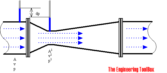
With proper instrumentation and flow calibrating, the Venturi Tube flowrate can be reduced to about 10% of its full scale range with proper accuracy. This provides a Turn Down Rate 10:1. Note that the manometry for a venturi tube or orifice should be installed below the hydraulic grade line or pipe.
Flow Nozzles
Flow nozzles are often used as measuring elements for air and gas flow in industrial applications.
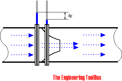
The flow nozzle is relative simple and cheap, and available for many applications in many materials.
The Turn Down Ratio and accuracy can be compared with the orifice plate.
The Sonic Nozzle - Critical (Choked) Flow Nozzle
When a gas accelerates through a nozzle, the velocity increase and the pressure and the gas density decrease. The maximum velocity is achieved at the throat, the minimum area, where it breaks Mach 1 or sonic. At this point it's not possible to increase the flow by lowering the downstream pressure. The flow is choked.
This situation is used in many control systems to maintain fixed, accurate, repeatable gas flow rates unaffected by the downstream pressure.
Recovery of Pressure Drop in Orifices, Nozzles and Venturi Meters
After the pressure difference has been generated in the differential pressure flow meter, the fluid pass through the pressure recovery exit section, where the differential pressure generated at the constricted area is partly recovered.
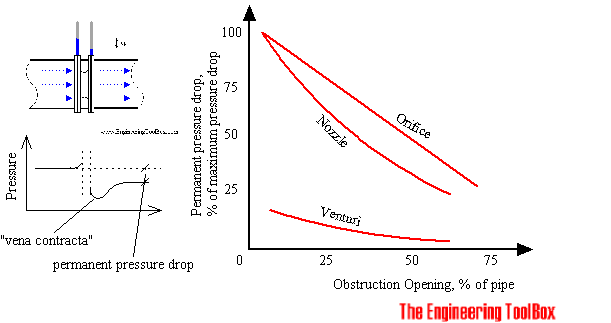
As we can see, the pressure drop in orifice plates are significant higher than in the venturi tubes.
Variable Area Flowmeter or Rotameter
The rotameter consists of a vertically oriented glass (or plastic) tube with a larger end at the top, and a metering float which is free to move within the tube. Fluid flow causes the float to rise in the tube as the upward pressure differential and buoyancy of the fluid overcome the effect of gravity.
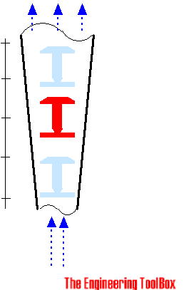
The float rises until the annular area between the float and tube increases sufficiently to allow a state of dynamic equilibrium between the upward differential pressure and buoyancy factors, and downward gravity factors.
The height of the float is an indication of the flow rate. The tube can be calibrated and graduated in appropriate flow units.
The rotameter meter typically have a TurnDown Ratio up to 12:1. The accuracy may be as good as 1% of full scale rating.
Magnetic floats can be used for alarm and signal transmission functions.
Velocity Flowmeters
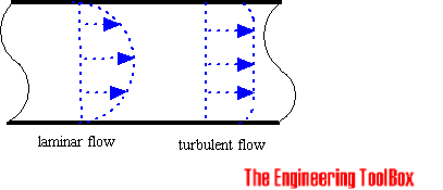
In a velocity flowmeter the flow is calculated by measuring the speed in one or more points in the flow, and integrating the flow speed over the flow area.
Pitot Tubes
The pitot tube are one the most used (and cheapest) ways to measure fluid flow, especially in air applications like ventilation and HVAC systems, even used in airplanes for speed measurent.
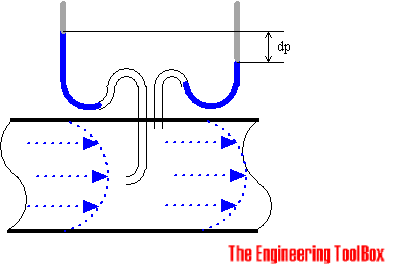
The pitot tube measures the fluid flow velocity by converting the kinetic energy of the flow into potential energy.
The use of the pitot tube is restricted to point measuring. With the "annubar", or multi-orifice pitot probe, the dynamic pressure can be measured across the velocity profile, and the annubar obtains an averaging effect.
Calorimetric Flowmeter
The calorimetric principle for fluid flow measurement is based on two temperature sensors in close contact with the fluid but thermal insulated from each other.
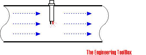
One of the two sensors is constantly heated and the cooling effect of the flowing fluid is used to monitor the flowrate. In a stationary (no flow) fluid condition there is a constant temperature difference between the two temperature sensors. When the fluid flow increases, heat energy is drawn from the heated sensor and the temperature difference between the sensors are reduced. The reduction is proportional to the flow rate of the fluid.
Response times will vary due the thermal conductivity of the fluid. In general lower thermal conductivity require higher velocity for proper measurement.
The calorimetric flowmeter can achieve relatively high accuracy at low flow rates.
Turbine Flowmeter
There is many different manufacturing design of turbine flow meters, but in general they are all based on the same simple principle:
If a fluid moves through a pipe and acts on the vanes of a turbine, the turbine will start to spin and rotate. The rate of spin is measured to calculate the flow.
The turndown ratios may be more than 100:1 if the turbine meter is calibrated for a single fluid and used at constant conditions. Accuracy may be better than +/-0,1%.
Vortex Flow Meter
An obstruction in a fluid flow creates vortices in a downstream flow. Every obstruction has a critical fluid flow speed at which vortex shedding occurs. Vortex shedding is the instance where alternating low pressure zones are generated in the downstream.

These alternating low pressure zones cause the obstruction to move towards the low pressure zone. With sensors gauging the vortices the strength of the flow can be measured.
- The Vortex Flowmeter Principle - An introduction to the vortex flowmeter principle.
Electromagnetic Flowmeter
An electromagnetic flowmeter operate on Faraday's law of electromagnetic induction that states that a voltage will be induced when a conductor moves through a magnetic field. The liquid serves as the conductor and the magnetic field is created by energized coils outside the flow tube.
The voltage produced is directly proportional to the flow rate. Two electrodes mounted in the pipe wall detect the voltage which is measured by a secondary element.
Electromagnetic flow meters can measure difficult and corrosive liquids and slurries, and they can measure flow in both directions with equal accuracy.
Electromagnetic flow meters have a relatively high power consumption and can only be used for electrical conductive fluids as water.
- The Electromagnetic Flow meter Principle - An introduction to the electromagnetic flow meter principle
Ultrasonic Doppler Flowmeter
The effect of motion of a sound source and its effect on the frequency of the sound was observed and described by Christian Johann Doppler.
The frequency of the reflected signal is modified by the velocity and direction of the fluid flow
If a fluid is moving towards a transducer, the frequency of the returning signal will increase. As fluid moves away from a transducer, the frequency of the returning signal decrease.
The frequency difference is equal to the reflected frequency minus the originating frequency and can be use to calculate the fluid flow speed.
- The Ultrasonic Doppler and Time of Flight Flow meter
Positive Displacement Flow meter
The positive displacement flow meter measures process fluid flow by precision-fitted rotors as flow measuring elements. Known and fixed volumes are displaced between the rotors. The rotation of the rotors are proportional to the volume of the fluid being displaced.
The number of rotations of the rotor is counted by an integral electronic pulse transmitter and converted to volume and flow rate.
The positive displacement rotor construction can be done in several ways:
- Reciprocating piston meters are of single and multiple-piston types.
- Oval-gear meters have two rotating, oval-shaped gears with synchronized, close fitting teeth. A fixed quantity of liquid passes through the meter for each revolution. Shaft rotation can be monitored to obtain specific flow rates.
- Nutating disk meters have movable disks mounted on a concentric sphere located in spherical side-walled chambers. The pressure of the liquid passing through the measuring chamber causes the disk to rock in a circulating path without rotating about its own axis. It is the only moving part in the measuring chamber.
- Rotary vane meters consists of equally divided, rotating impellers, two or more compartments, inside the meter's housings. The impellers are in continuous contact with the casing. A fixed volume of liquid is swept to the meter's outlet from each compartment as the impeller rotates. The revolutions of the impeller are counted and registered in volumetric units.
The positive displacement flowmeter may be used for all relatively nonabrasive fluids such as heating oils, lubrication oils, polymer additives, animal and vegetable fat, printing ink, Dichlorodifluoromethane R-12, and many more.
Accuracy may be up to 0.1% of full rate with a TurnDown of 70:1 or more.
Mass Flowmeters
Mass meters measure the mass flow rate directly.
Thermal Flowmeter
The thermal mass flowmeter operates independent of density, pressure, and viscosity. Thermal meters use a heated sensing element isolated from the fluid flow path where the flow stream conducts heat from the sensing element. The conducted heat is directly proportional to the mass flow rate and the temperature difference is calculated to mass flow.
The accuracy of the thermal mass flow device depends on the calibrations reliability of the actual process and variations in the temperature, pressure, flow rate, heat capacity and viscosity of the fluid.
Coriolis Flowmeter
Direct mass measurement sets Coriolis flowmeters apart from other technologies. Mass measurement is not sensitive to changes in pressure, temperature, viscosity and density. With the ability to measure liquids, slurries and gases, Coriolis flowmeters are universal meters.
Coriolis Mass Flowmeter uses the Coriolis effect to measure the amount of mass moving through the element. The fluid to be measured runs through a U-shaped tube that is caused to vibrate in an angular harmonic oscillation. Due to the Coriolis forces, the tubes will deform and an additional vibration component will be added to the oscillation. This additional component causes a phase shift on some places of the tubes which can be measured with sensors.
The Coriolis flow meters are in general very accurate, better than +/-0,1% with an turndown rate more than 100:1. The Coriolis meter can also be used to measure the fluids density.
Open Channel Flowmeters
A common method of measuring flow through an open channel is to measure the height of the liquid as it passes over an obstruction as a flume or weir in the channel.
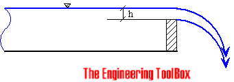
Common used is the Sharp-Crested Weir, the V-Notch Weir, the Cipolletti weir, the Rectangular-Notch Weir, the Parshall Flume or Venturi Flume.
- Weir Flow Measurement Standards - Important and common used standards within weir flow measurement
- Measuring Flow Rate with Weirs - Weirs are often used for measuring flow rates in open channels and rivers in connection to water supply and sewage plants
- Weir Flow Measurement Standards - Important and common used standards within weir flow measurement
Selection Considerations
Important factors when selecting flow metering devices are
- accuracy
- cost
- legal contraints
- flow rate range
- head loss
- operating requirements
- maintenance
- life time
These factors are more or less related to each other. Example - cost of flow meters increases with accuracy and life time quality.


