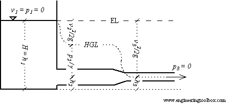
Energy and Hydraulic Grade Line
The hydraulic grade line and the energy line are graphical presentations of the Bernoulli equation.
The Bernoulli Equation
For steady, inviscid (having zero viscosity), incompressible flow the total energy remains constant along a stream line as expressed with the Bernoulli Equation:
p + 1/2 ρ v2 + γ h = constant along a streamline (1)
where
p = static pressure (relative to the moving fluid) (Pa, N/m2)
ρ = density (kg/m3)
γ = specific weight of fluid (N/m3)
v = flow velocity (m/s)
g = acceleration of gravity (9.81 m/s2)
h = elevation height (m)
Each term of this equation has the dimension force per unit area - N/m2 or psi, lb/ft2 in Imperial units.

The Head
By dividing each term with the specific weight - γ = ρ g - equation (1) can be transformed to express head as
p / γ + v2 / 2 g + h = constant along a streamline = H (2)
where
H = the total head (m fluid column)
Each term of this equation has the dimension length - m or ft in Imperial units.
Note! - the head unit is with reference to the density of the flowing fluid. For other units - like mm Water Column - check Velocity Pressure Head.
The Total Head
(2) states that the sum of
- pressure head - p / γ
- velocity head - v2/ 2 g
- elevation head - h
is constant along a stream line. This constant can be called the total head - H.
The total head in a flow can be determined by measuring the stagnation pressure using a pitot tube.
The Piezometric Head
The sum of pressure head - p / γ - and elevation head - h - is called the piezometric head. The piezometric head in a flow can be measured through an flat opening parallel to the flow.
The Energy Line
The Energy Line is a line that represent the total head available to the fluid and can be expressed as:
EL = H = p / γ + v2 / 2 g + h = constant along a streamline (3)
where
EL = Energy Line (m fluid column)
For a fluid flow without any losses due to friction (major losses) or components (minor losses) - the energy line would be at a constant level. In a practical world the energy line decreases along the flow due to losses.
A turbine in the flow reduces the energy line and a pump or fan in the line increases the energy line.
The Hydraulic Grade Line
The Hydraulic Grade Line is a line representing the total head available to the fluid - minus the velocity head and can be expressed as:
HGL = p / γ + h (4)
where
HGL = Hydraulic Grade Line (m fluid column)
The hydraulic grade line lies one velocity head below the the energy line.


