Engineering ToolBox - Resources, Tools and Basic Information for Engineering and Design of Technical Applications!

Compressed Air Piping - Pressure Loss Diagrams, Imperial Units

Pressure drop in compressed air pipelines with applied pressure 50, 100 and 150 psi.

Pressure drop in psi per 100 ft compressed air pipeline can be estimated for some typical entering pressures in the diagrams below. The diagrams are calculated for schedule 40 pipes.

Other dimensions or pressures can be calculated with the

Applied Pressure 50 psig
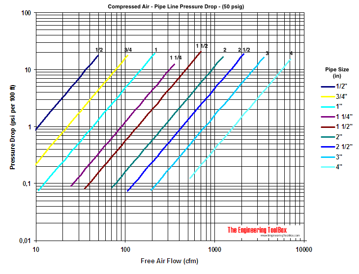
compressed air pipeline pressure drop diagram 50 psig

Download and print Compressed Air - Pipe Line Pressure Drop (gauge Pressure 50 psig)

  • 1 ft (foot) = 0.3048 m
  • 1 cfm = 1.7 m3/h = 0.028 m3/min
  • 1 psi = 0.069 bar = 0.070 kg/cm2

Applied Pressure 100 psig
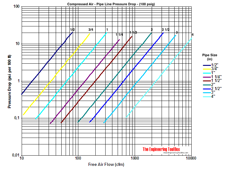
compressed air pipeline pressure drop diagram 100 psig

Download and print Compressed Air - Pipe Line Pressure Drop (gauge Pressure 50 psig)

Applied Pressure 150 psig
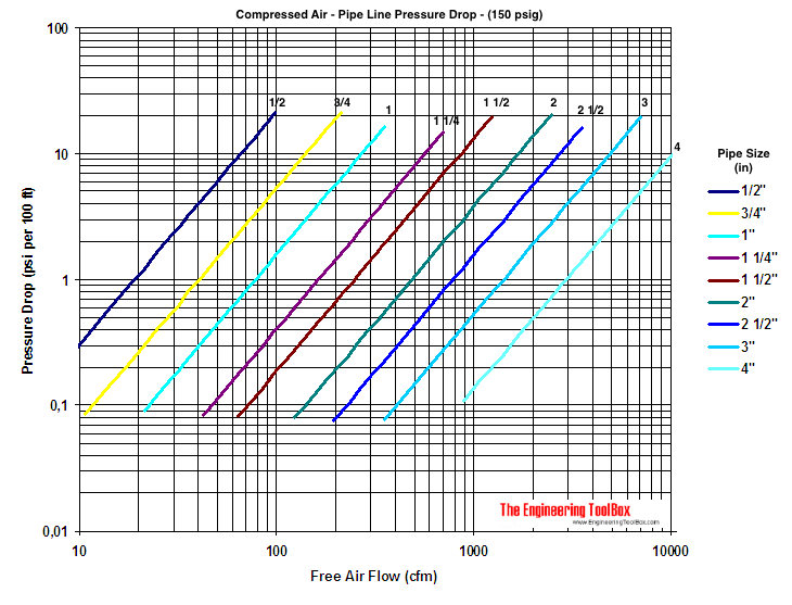
compressed air pipeline pressure drop diagram 150 psig

Download and print Compressed Air - Pipe Line Pressure Drop (gauge Pressure 50 psig)

The SCFM - Standard Cubic Feet per Minute - determines the weight of air to fixed or "Standard" conditions. There are several definitions of SCFM. The most commonly used in the United States is based on the properties

  • 14.696 Pounds per Square Inch (psia)
  • 60 Degrees Fahrenheit (oF)
  • 0% Relative Humidity (RH)

Europeans normally use one ATA and 0oC as SCFM.

Compressed Air Pipe Line Pressure Loss other Dimensions

Compressed air pressure drop in pipes with other dimensions than schedule 40 can be calculated from

dp = dp40 (d40 / d)5                                          (1)

where

dp = actual pressure drop (psi per 100 ft pipe)

dp40 = pressure drop in schedule 40 pipe from the table or diagram above (psig per 100 ft pipe)

d40 = inside diameter schedule 40 pipe (inches)

d = actual inside diameter (inches)

Related Topics

Related Documents

Search

Search is the most efficient way to navigate the Engineering ToolBox.

Engineering ToolBox - SketchUp Extension - Online 3D modeling!

3D Engineering ToolBox Extension to SketchUp - add parametric components to your SketchUp model

Add standard and customized parametric components - like flange beams, lumbers, piping, stairs and more - to your Sketchup model with the Engineering ToolBox - SketchUp Extension - enabled for use with older versions of the amazing SketchUp Make and the newer "up to date" SketchUp Pro . Add the Engineering ToolBox extension to your SketchUp Make/Pro from the Extension Warehouse !

Translate this Page

Translate this page to Your Own Language .

About the Engineering ToolBox!

Privacy Policy

We don't collect information from our users. More about

We use a third-party to provide monetization technologies for our site. You can review their privacy and cookie policy here.

You can change your privacy settings by clicking the following button: .

Citation

This page can be cited as

  • The Engineering ToolBox (2003). Compressed Air Piping - Pressure Loss Diagrams, Imperial Units. [online] Available at: https://www.engineeringtoolbox.com/compressed-air-pipe-pressure-d_36.html [Accessed Day Month Year].

Modify the access date according your visit.

3D Engineering ToolBox - draw and model technical applications! 2D Engineering ToolBox - create and share online diagram drawing templates! Engineering ToolBox Apps - mobile online and offline engineering applications!

Unit Converter


11.4.12

.