Compressed Air Receivers
Calculating air receivers capacity.
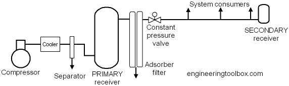
An air receiver is essential to every compressed air system to act as a buffer and a storage medium between the compressor and the consumption system. There are in principal two different air receivers in a compressed air system:
- PRIMARY receiver - located near the compressor, after the after-cooler but before filtration and drying equipment
- SECONDARY receivers - located close to points of larger intermittent air consumption
The maximum capacity of the compressor in a well designed systems always exceed the maximum mean air consumption of the system (maximum mean air consumption is the mean air consumption over some reasonable time).
Since the maximum capacity of an air compressor also always exceed the minimum air consumption in the system - the compressor must modulate its capacity during normal work, often by using primitive strategies as on/off modulating or more advanced strategies as frequency drives and inverters. Primitive modulating strategies cause more pressure variations in compressed air systems than more advanced strategies.
In addition, the air consumption vary due to the process supported. In shorter periods the demand for compressed air may even exceed the maximum capacity of the compressor. In fact, it is common in well designed systems not to design the compressor for the maximum peek loads.
Air receivers in compressed air systems serves the important purposes of
- equalizing the pressure variation from the start/stop and modulating sequence of the compressor
- storage of air volume equalizing the variation in consumption and demand from the system
In addition the receiver serve the purpose of
- collecting condensate and water in the air after the compressor
Sizing the Air Receiver
The air receiver must in general be sized according
- the variation in the consumption demand
- the compressor size and the modulation strategy
In general it is possible to calculate the maximum consumption in the system by summarizing the demand of each consumer. The summarized consumption must be multiplied with a
- usage factor ranging 0.1 - 1
depending on the system. In practice it is common that the manufacturer use standardized receivers for specific compressor models based on their know-how.
For calculating the receiver, note that it is necessary with a pressure band for the receiver to be effective. If the consumption process requires 100 psig (6.9 bar) and the compressor is set to 100 psig , there is no storage and no buffer. Any increased demand will make a pressure drop below 100 psig until the compressor responds by increasing the air volume compressed.
If the compressors operates at 110 psig the difference between 110 psig and 100 psig accounts for the air stored in the receiver. If the demand increases, the pressure can drop 10 psig before the minimum requirement is met. Pressure and flow controllers can be used after the receiver for stabilizing downstream pressure to 100 psig and flattening demand peaks. Note that in a compressed air system the pipe work also makes the purpose of a buffered volume.
There is no generally accepted method of sizing air receivers but a commonly used formula is based on the mass balance
C pa t = V (p1 - p2) (1)
that can be transformed to
t = V (p1 - p2) / (C pa) (1b)
where
V = volume of the receiver tank (cu ft)
t = time for the receiver to go from upper to lower pressure limits (min)
C = free air needed (scfm)
pa = atmosphere pressure (14.7 psia)
p1 = maximum tank pressure (psia)
p2= minimum tank pressure (psia)
Example - Sizing an Air Receiver
For an air compressor system with mean air consumption 1000 cfm , maximum tank pressure 110 psi , minimum tank pressure 100 psi and 5 sec time for the receiver to go from upper to lower pressure - the volume of the receiver tank can be calculated by modifying (1) to
V = t C pa / (p1 - p2)
= (5 sec) (1/60 min/sec) (1000 cfm) (14.7 psi) / ((110 psi) - (100 psi))
= 122 ft3
It is also common to size receivers
- to 1 gallon for each ACFM (Actual Cubic Feet per Minute), or
- 4 gallons per compressor hp (horse power)
Note! Receivers of unsound or questionable constructions may be very dangerous.

Air Receiver Capacity
| Tank Size (inches) | Tank Size (gallons) | Air Receiver Capacity (cubic feet) | |||
|---|---|---|---|---|---|
| Gauge Pressure on Tank (psig) | |||||
| 0 | 100 | 150 | 200 | ||
| 12 x 24 | 10 | 1.3 | 11 | 15 | 19 |
| 14 x 36 | 20 | 2.7 | 21 | 30 | 39 |
| 16 x 36 | 30 | 4.0 | 31 | 45 | 59 |
| 20 x 48 | 60 | 8.0 | 62 | 90 | 117 |
| 20 x 63 | 80 | 11 | 83 | 120 | 156 |
| 24 x 68 | 120 | 16 | 125 | 180 | 234 |
| 30 x 84 | 240 | 32 | 250 | 360 | 467 |
- 1 ft3 = 0.02832 m3
- 1 inch = 25.4 mm
- 1 psig = 6.9 kPa = 0.069 bar
- 1 Gallon (U.S.) = 3.785×10⁻³ m3 = 3.785 dm3 (liter) = 231 in3


