Engineering ToolBox - Resources, Tools and Basic Information for Engineering and Design of Technical Applications!

Pneumatic Piping - Pressure Loss vs. Air Flow

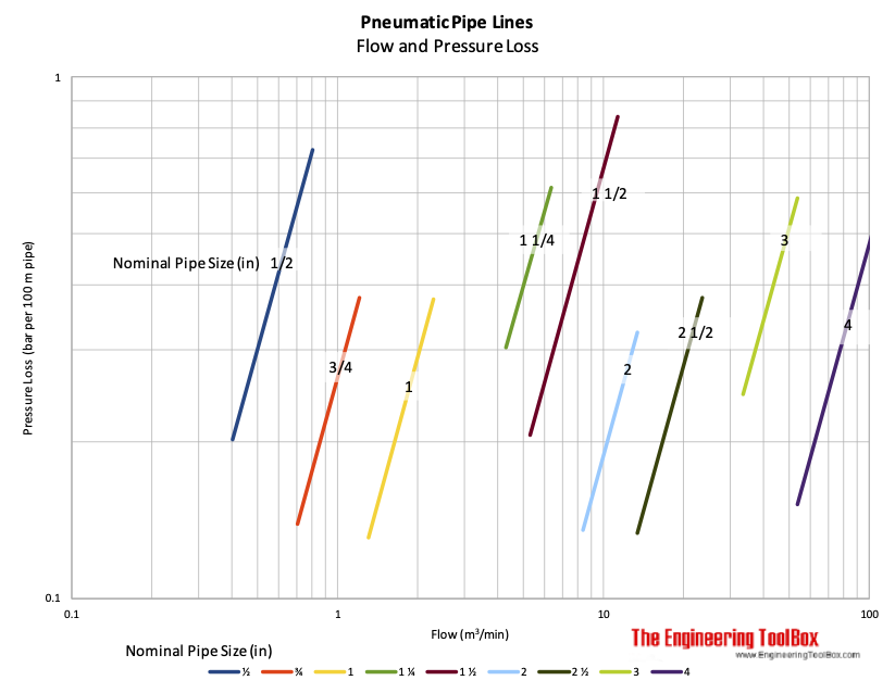
Pressure loss in pneumatic tubes - sizes ranging 5 - 36 mm.

Pressure loss in pneumatic pipe lines are indicated below. The diagram is calculated for


Pneumatic pipes and tubes - pressure loss chart in bar

Related Topics

Related Documents

Search

Search is the most efficient way to navigate the Engineering ToolBox.

Engineering ToolBox - SketchUp Extension - Online 3D modeling!

3D Engineering ToolBox Extension to SketchUp - add parametric components to your SketchUp model

Add standard and customized parametric components - like flange beams, lumbers, piping, stairs and more - to your Sketchup model with the Engineering ToolBox - SketchUp Extension - enabled for use with older versions of the amazing SketchUp Make and the newer "up to date" SketchUp Pro . Add the Engineering ToolBox extension to your SketchUp Make/Pro from the Extension Warehouse !

Translate this Page

Translate this page to Your Own Language .

About the Engineering ToolBox!

Privacy Policy

We don't collect information from our users. More about

We use a third-party to provide monetization technologies for our site. You can review their privacy and cookie policy here.

You can change your privacy settings by clicking the following button: .

Citation

This page can be cited as

  • The Engineering ToolBox (2011). Pneumatic Piping - Pressure Loss vs. Air Flow. [online] Available at: https://www.engineeringtoolbox.com/pneumatics-pipes-pressure-loss-d_1770.html [Accessed Day Month Year].

Modify the access date according your visit.

3D Engineering ToolBox - draw and model technical applications! 2D Engineering ToolBox - create and share online diagram drawing templates! Engineering ToolBox Apps - mobile online and offline engineering applications!

Unit Converter


4.19.9

.