Compressed Air - Pipe Line Pressure Drop Diagram
Calculate pressure drop in compressed air pipe lines with a nomograph diagram.
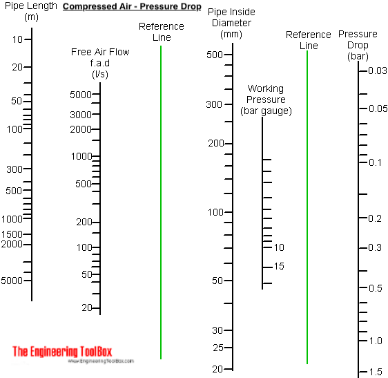
The nomograph diagram below can be used to estimate pressure drop in compressed air pipe lines:
Download and print Compressed Air - Pipe Line Pressure Drop Diagram
Example - Pressure Drop in Compressed Air Pipeline
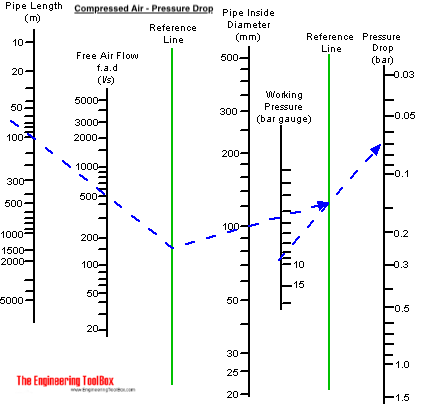
The pressure drop in a compressed air pipe line
- length 100 m
- air flow 500 l/s
- inside diameter 100 mm
- working pressure 9 bar gauge
can be estimated in the diagram by drawing a line from the length line through the air flow volume line to the reference line. From the point on the reference line draw a line through the pipe diameter line to the reference line. From the working pressure line draw a line through the point on the reference line to the pressure drop line.
As indicated below the pressure drop can be estimated to 0.07 bar.
Related Topics
-
Gases and Compressed Air
Properties of air, LNG, LPG and other common gases. Pipeline capacities and sizing of relief valves.
Related Documents
-
Compressed Air - Laboratory Consumption
Compressed air supply to laboratories. -
Compressed Air - Pipe Line Pressure Loss - Online Calculator with Metric and Imperial Units
Calculate pressure drop in compressed air pipe lines - metric and imperial units. -
Compressed Air Pipe Line Capacity
Capacities of compressed air pipelines - pressure ranging 5 - 250 psi (0.5 - 17 bar). -
Compressed Air Pipe Lines - Pressure Loss vs. Capacity and Operating Pressure
Pressure drop in compressed air pipe lines. -
Compressed Air Pipes - Fittings and Pressure Loss
Fittings in compressed air pipe lines and equivalent length pressure drop. -
Compressed Air Piping - Pressure Loss Diagrams, Imperial Units
Pressure drop in compressed air pipelines with applied pressure 50, 100 and 150 psi. -
Compressed Air vs. Free Air - Compression Ratio
The ratio of compressed air pressure to free air pressure.