Pressure Gradient Diagrams
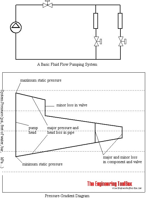
Static pressure graphical presentation throughout a fluid flow system.
A pressure-gradient diagram includes only the static and physical pressure in a system and the diagram is suitable for checking energy transformation for the flow through the system. Velocity head is dynamic head and not included as in the Energy and Hydraulic Grade Line Diagram.
The vertical dimension in the pressure-gradient diagram is in scale with the pressure or head unit used for the system. The horizontal dimension is not in scale and is used to separate the specific head and pressure losses through the system.
A pressure-gradient diagram for a basic circulation pump system is illustrated below.

The horizontal falling lines in the diagram visualizes the major head or pressure loss due to friction in the pipes. The vertical lines visualizes the minor head or pressure loss due to valves and components. The vertical lines are important for the sizing of reduction valves needed for balancing the system.
The diagram above shows a static steady state stabilized flow where the flow rate and the minor and major head or pressure losses are constant. In reality it is more common today with modulating systems where flow rates changes due to external conditions - as in heating systems when it's get colder or warmer, or in domestic water supply systems where the demand of water changes over the day.
The pressure-gradient diagram should be drawn for
- the normal condition with normal flow rate
- the extreme condition where the pump deliver a maximum flow rate at the lowest pump head
- the extreme condition where the pump deliver a minimum flow rate at the highest pump head
Analyzing the minimum and maximum conditions is important when designing reduction valves needed to balancing the system. it is also important for an optimized design of modulating control valves in the system.


