Pipes - Insulated Heat Loss Diagrams
Heat loss (W/ft) diagrams for 1/2 to 6 inches insulated pipes - ranging insulation thickness 0.5 to 4 inches and temperature differences 50 to 350 degF.
The heat loss diagrams below is based on metal pipes with fiber glass insulation, thermal conductivity 0.25 Btu/h oF ft2/in and outdoor condition with moderate wind 20 mph. A safety factor of 10% is included.
- indoor location - reduce values with 10%
- mineral wool insulation - increase values with 6%
- rigid cellular polyurethane - reduce values by 30%
- Heat loss diagram (W/ft)
Pipe Heat Loss - Insulation thickness 4 inches
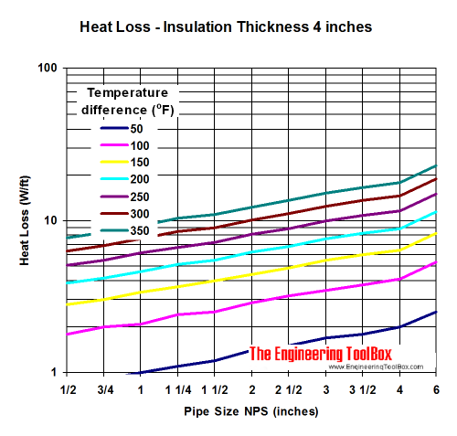
- 1 W/ft = 3.41 Btu/h ft = 3.28 W/m
- 1 oF = 0.555 oC
Pipe Heat Loss - Insulation thickness 3 inches
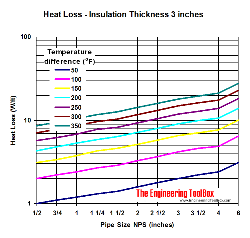
Pipe Heat Loss - Insulation thickness 2.5 inches
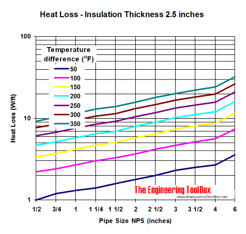
Pipe Heat Loss - Insulation thickness 2 inches
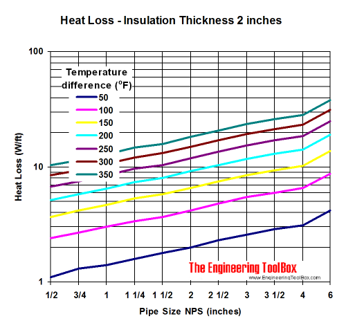
Pipe Heat Loss - Insulation thickness 1.5 inches
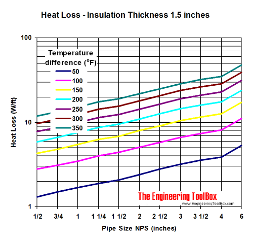
Pipe Heat Loss - Insulation thickness 1 inch
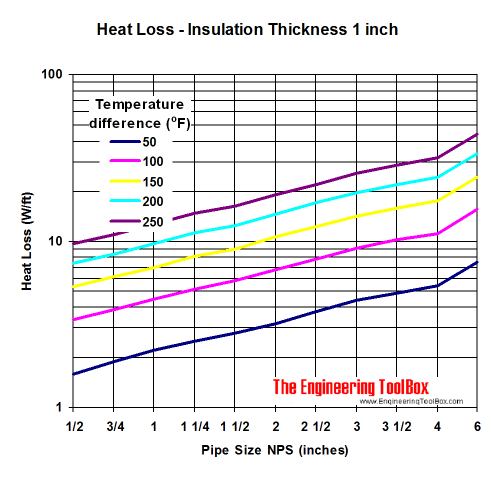
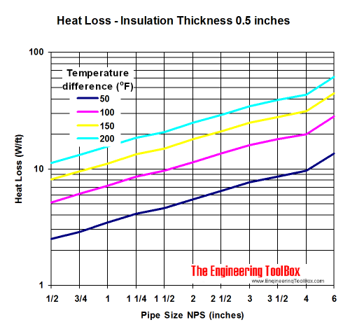
Pipe Heat Loss - Insulation thickness 0.5 inches
Related Topics
-
Heat Loss and Insulation
Heat loss from pipes, tubes and tanks - with and without insulation. Use of materials lke foam, fiberglass, rockwool and more. -
Insulation
Calculate heat transfer and heat loss from buildings and technical applications. Heat transfer coefficients and insulation methods available for reduction of energy consumption. -
Insulation and Heat Loss from Steam and Condesate Pipe Lines
Heat loss from uninsulated and insulated steam and condensate pipes and tanks. Calculate insulation thicknesses.
Related Documents
-
Calcium Silicate Insulation
Thermal conductivity of calcium silicate insulation - temperature and k-values. -
Copper Tubes - Heat Losses
Heat loss from uninsulated copper tubes vs. temperature differences between tube and air. -
Copper Tubes - Uninsulated Heat Losses
Heat loss from uninsulated copper pipes - dimensions ranging 1/2 - 4 inches. -
Heat Loss from Oil Filled Tanks and Pipe Lines
Heat loss from insulated and non insulated sheltered and exposed oil tanks and pipes. -
Heat Traced Pipes - Wrapping Factor
Wrapping factor when the heat loss from a pipe or tube is higher than the capacity of the heat trace cable. -
Insulated Copper Tubes - Heat Loss
Heat loss to surrounding air from insulated copper tubes. -
Mineral Wool Insulation
Thermal conductivity - k-values - vs. temperature. -
Oil Filled Tanks - Heat Loss
Heat loss from insulated and uninsulated, sheltered and exposed heated oil tanks. -
Pipes - Insulated Heat Loss Diagrams
Heat loss (W/m) from 1/2 to 6 inches insulated pipes - ranging insulation thickness 10 to 80 mm and temperature differences 20 to 180 degC. -
Pipes and Cylinders - Conductive Heat Losses
Conductive heat losses through cylinder or pipe walls. -
Polyurethane Insulation
Thermal conductivity - k-values - vs. temperature. -
Steam Pipes - Heat Losses
The amount of condensate generated in a steam pipe depends on the heat loss from the pipe to the surroundings. -
Steam Pipes - Heat Losses (W/m)
Heat losses from un-insulated steam pipes. -
Steam Tracing Pipe Lines
Steam tracing of pipe lines can be done to maintain appropriate product temperatures. -
Steel Pipes - Heat Loss Diagram
Heat loss from steel pipes and tubes - dimensions 1/2 to 12 inches.


