Electrical Resistance in Serial and Parallel Networks
Resistors in parallel and serial connections.
Serial Connection
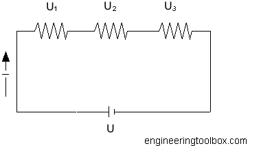
The total resistance for resistors connected in series can be calculated as
R = R1 + R2 + .... + Rn (1)
where
R = resistance (ohm, Ω)
Example - Resistors in Series
Three resistors 33 ohm , 33 ohm and 47 ohm are connected in serial. The total resistance can be calculated as
R = (33 ohm) + (33 ohm) + (47 ohm)
= 113 ohm
Standard resistors are available with
- resistances from 0.0002 Ω through 1012 Ω
- power ratings from 1/8 watt through 250 watts
- accuracies from 0.005% through 20%
Parallel Connection

The total resistance for resistors connected in parallel can be calculated as
1 / R = 1 / R1 + 1 / R2 + .... + 1 / Rn (2)
Equivalent resistance of 2 resistors connected in parallel can be expressed as
R = R1 R2 / (R1 + R2) (3)
Example - Resistors in Parallel
Three resistors 33 ohm , 33 ohm and 47 ohm are connected in parallel. The total resistance can be calculated as
1 / R = 1 / (33 ohm) + 1 / (33 ohm) + 1 / (47 ohm)
= 0.082 (1 / ohm)
R = 1 / (0.082 ohm)
= 12.2 ohm
If the battery voltage is 12 V - the current through the circuit can be calculated by using Ohm's law
I = U / R
= (12 V) / (12.2 ohm)
= 0.98 ampere
The current through each resistor can be calculated
I1 = U / R1 = (12 V) / (33 ohm) = 0.36 ampere
I2= U / R2= (12 V) / (33 ohm) = 0.36 ampere
I3 = U / R3 = (12 V) / (47 ohm) = 0.26 ampere
Resistors Connected in Parallel - Calculator
Add the resistances for up to five parallel connected resistors and (optionally) the circuit voltage.
The total resistance and current - and the individual currents in all resistors - will be calculated:
Power Dissipated by a Resistor
The power dissipated by a resistor can be expressed as
P = U I
= R I2
= U2 / R (4)
where
P = power (W, Js)
Thévenin Equivalent Circuit
Thévenin’s theorem states that
- any two-terminal network of resistors and voltage sources is equivalent to a single resistor R in series with a single voltage source V.

The voltage divider can be regarded as a Thévenin Equivalent Circuit where the internal arrangement of resistors and the input voltage source equivalents so a single source and a single resistor.


