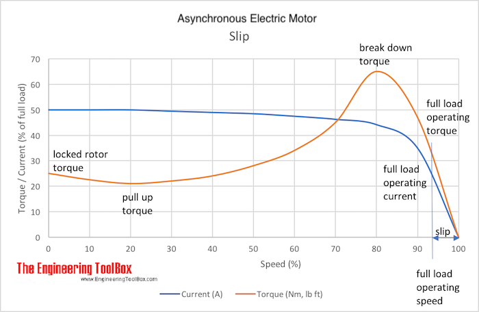
Electrical Induction Motors - Slip
Slip is the difference between an electrical induction motor's synchronous and asynchronous speed.
An AC (Alternating Current) induction motor consists of a stator and a rotor and the interaction of the currents flowing in the rotor bars and the rotating magnetic field in the stator generates the torque that turns the motor. In normal operation with a load the rotor speed always lags the magnetic field's speed allowing the rotor bars to cut magnetic lines of force and produce a useful torque.
The difference between the synchronous speed of the electric motor magnetic field, and the shaft rotating speed is slip - measured in RPM or frequency.
Slip increases with increasing load - providing a greater torque.

It is common to express the slip as the ratio between the shaft rotation speed and the synchronous magnetic field speed.
s = (ns - na) 100% / ns (1)
where
s = slip
ns = synchronous speed of magnetic field (rev/min, rpm)
na = shaft rotating speed (rev/min, rpm)
When the rotor is not turning the slip is 100%.
Full-load slip varies from less than 1 % in high hp motors to more than 5-6 % in minor hp motors.
| Motor Size (hp) | 0.5 | 5 | 15 | 50 | 250 |
|---|---|---|---|---|---|
| Typical Slip (%) |
5 | 3 | 2.5 | 1.7 | 0.8 |
Number of poles, frequencies and synchronous induction motor speed
| No. of Magnetic Poles | Speed (rpm) | |
|---|---|---|
| Frequency (Hz) | ||
| 50 | 60 | |
| 2 | 3000 | 3600 |
| 4 | 1500 | 1800 |
| 6 | 1000 | 1200 |
| 8 | 750 | 900 |
| 10 | 600 | 720 |
| 12 | 500 | 600 |
| 16 | 375 | 450 |
| 20 | 300 | 360 |
Slip and Voltage
When a motor starts to rotate the slip is 100% and the motor current is at maximum. Slip and motor current are reduced when the rotor begin turning.
Slip Frequency
Frequency decreases when slip decrease.
Slip and Inductive Reactance
Inductive reactance depends on the frequency and the slip. When the rotor is not turning the slip frequency is at maximum and so is the inductive reactance.
A motor has a resistance and inductance and when the rotor is turning the inductive reactance is low and the power factor approaches to one.
Slip and Rotor Impedance
The inductive reactance will change with the slip since the rotor impedance is the phase sum of the constant resistance and the variable inductive reactance.
When the motor starts rotating the inductive reactance is high and impedance is mostly inductive. The rotor has a low lagging power factor. When the speed increases the inductive reactance goes down equaling the resistance.
Classification of Induction Motors
Electrical induction motors are designed for different applications regarding characteristics like breakaway torque, pull-up torque, slip and more - check NEMA A, B, C and D classification of electrical inductions motors.


