P&ID - Piping and Instrumentation Diagram
Schematic illustration of a functional relationship between piping, instrumentation and system components.
P&ID's shows all piping including physical sequences of branches, reducers, valves, equipment, instrumentation and control interlocks.
The P&ID's are used to operate process systems.
A P&ID should include:
- Instrumentation and designations
- Mechanical equipment with names and numbers
- All valves and their identifications
- Process piping, sizes and identification
- Miscellaneous - vents, drains, special fittings, sampling lines, reducers, increasers and swagers
- Permanent start-up and flush lines
- Flow directions
- Interconnections references
- Control inputs and outputs, interlocks
- Interfaces for class changes
- Seismic category
- Quality level
- Annunciation inputs
- Computer control system input
- Vendor and contractor interfaces
- Identification of components and subsystems delivered by others
- Intended physical sequence of the equipment
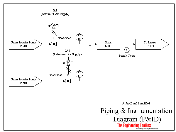
The figure below illustrates a very small and simplified P&ID:
A P&ID should not include:
- Equipment rating or capacities
- Instrument root valves
- Control relays
- Manual switches and indicating lights
- Primary instrument tubing and valves
- Pressure temperature and flow data
- Elbows and similar standard fittings
- Extensive explanatory notes
Insert piping components to your Sketchup model with the Engineering ToolBox Sketchup Extension
Related Topics
-
Design Strategies for Piping Systems
Piping systems design strategies - documentation, P&ID, flow diagrams - capacities and limits. -
Drawing Tools
2D and 3D engineering drawing tools. -
Measurements and Instrumentation
Measurement and instrumentation strategies. -
Process Control Systems
Instrumentation, design and documentation of process control systems. -
Process Control Systems Documentation
Documentation of process control systems - Block Flow Diagrams (BFD), Process Flow Diagrams (PFD), Piping and Instrumentation Diagrams (P&ID) and more.
Related Documents
-
BFD - Block Flow Diagram
A Block Flow Diagram is a schematic illustration of a major process. -
Commissioning
Commissioning is methodical procedures and methods for documenting and testing performance of a technical system. -
Contract Types
Commonly used engineering and construction contracts. -
CSI MasterFormat Specifications
Construction Specifications Institute's 2004 Master-Format Edition. -
Greek Alphabet
The Greek alphabet is essential expressing formulas and in technical language. -
HVAC Diagram - Online Drawing Tool
Draw HVAC diagrams online with this Google Drive drawing tool. -
ISA Instrumentation Codes used in Process Control Systems
The ISA standards and symbols are important for the P&IDs and documents describing the process control system. -
P&ID Diagram - Online Drawing Tool
Draw P&ID diagrams online in the browser with Google Docs. -
PFD - Process Flow Diagram
The Process Flow Diagram (PFD) is a schematic illustration of a system. -
PFD - Process Flow Diagram - Online Drawing Tool
Draw Process Flow Diagrams with this online Google Docs drawing application. -
Pipe Legends - Identification Scheme
Color codes, field and legend. -
Process Controllers - P, PI & PID
Proportional, integrating and derivative process controllers. -
Process Instrumentation - ISA Codes
ISA process instrumentation codes - and combinations. -
Signal Transmission - Standards
Standard signals used for transmission from sensor to controller. -
Uniformat
The ASTM E1557 UNIFORMAT II Standard.