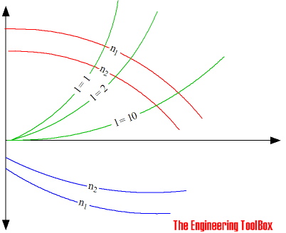
Fan Capacity Diagrams
Pressure, head, air flow volume and fan capacity diagrams.
Pressure head as function of air flow volume may be expressed in a diagram like the one below:

- red lines are pressure heads as function of air volume flow and speed of the fan
- green lines marked - l - are throttle lines
- blue lines are power consumption
Pressure and Head
Operation of fans are often expressed in terms of pressure
pt = ps + pd = constant (1)
where
pt = total pressure (Pa, N/m2)
ps = static pressure (Pa, N/m2)
pd = dynamic pressure (Pa, N/m2)
Dynamic pressure can be expressed as
pd = ρ v2 / 2 (2)
where
ρ = density of air (kg/m3)
v = flow velocity (m/s)

Head developed can be expressed as
dp = ps2 - ps1 + (v22 - v12) ρ / 2 (3)
where
subscription1 is the inlet of the fan and subscription2 is the outlet


