Air Ducts - Minor Loss Coefficient Diagrams
Minor loss coefficient diagrams for air ductwork, bends, expansions, inlets and outlets - SI units.
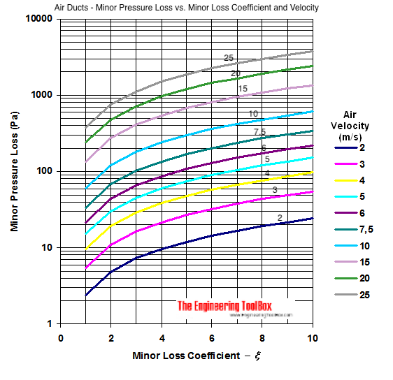
Minor loss in air ducts based on a summarized minor loss coefficients and air flow velocity:

Download and print Air Ducts - Minor Loss Diagram
- 1 Pa = 1 N/m2 = 1.4504x10⁻⁴ lb/in2 = 1x10⁻⁵ bar = 4.03x10⁻³ in water = 0.336x10⁻³ ft water = 0.1024 mm water = 0.295x10⁻³ in mercury = 7.55x10⁻³ mm mercury = 0.1024 kg/m2 = 0.993x10⁻⁵ atm
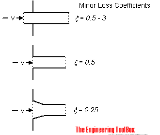
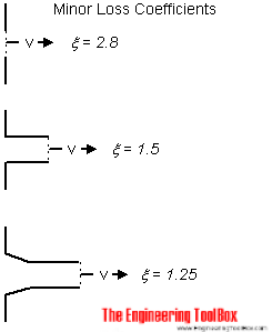
Minor loss for some common duct-work components like bends, expansions, inlets and outlets can be estimated from the diagrams below.
Minor Loss Coefficients - Bends
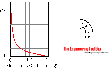
The minor loss coefficients in 90o bends can be estimated with the diagram below.

The minor loss in bends 0 - 180o can be estimated with the equation
ξ0-180 = ξ90 α / 90 (1)
where
ξ0-180 = minor loss coefficient for the bend with the actual angle
ξ90 = minor loss coefficient for the 90o bend according the diagram above
α = angle of the actual bend
The minor loss coefficient in a 90o bend like the one below is 1.0.

Minor Loss Coefficients - Expansions

Minor Loss Coefficients - Inlets

Minor Loss Coefficients - Outlets

Related Topics
-
Ventilation Systems
Design of systems for ventilation and air handling - air change rates, ducts and pressure drops, charts and diagrams and more.
Related Documents
-
Air Duct Components - Minor Dynamic Loss Coefficients
Minor loss (pressure or head loss) coefficients for air duct components. -
Air Duct Velocities
Typical air duct velocities in applications like ventilation systems or compressed air systems. -
Air Ducts - Friction Loss Diagram
A major friction loss diagram for air ducts - SI units. -
Energy Equation - Pressure Loss vs. Head Loss
Calculate pressure loss - or head loss - in ducts, pipes or tubes. -
Equivalent Length vs. Minor Pressure Head Loss in Pipe and Duct Components
Minor pressure and head loss in pipes vs. equivalent length in tubes and duct systems. -
Pipe and Tube System Components - Minor (Dynamic) Loss Coefficients
Minor loss coefficients for components used in pipe and tube systems. -
Rectangular Air Ducts - Velocity Diagram
Velocity diagram for rectangular air ducts - metric units. -
Ventilation Ducts - Minor Loss Resistance
Minor pressure or head loss in ventilation ducts vs. air velocity - minor loss coefficient diagram.


