Cantilever Beams - Moments and Deflections
Maximum reaction forces, deflections and moments - single and uniform loads.
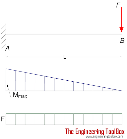
Cantilever Beam - Single Load at the End

Maximum Reaction Force
at the fixed end can be expressed as:
RA = F (1a)
where
RA = reaction force in A (N, lb)
F = single acting force in B (N, lb)
Maximum Moment
at the fixed end can be expressed as
Mmax = MA
= - F L (1b)
where
MA = maximum moment in A (Nm, Nmm, lb in)
L = length of beam (m, mm, in)
Maximum Deflection
at the end of the cantilever beam can be expressed as
δB = F L3 / (3 E I) (1c)
where
δB = maximum deflection in B (m, mm, in)
E = modulus of elasticity (N/m2 (Pa), N/mm2, lb/in2 (psi))
I = moment of Inertia (m4, mm4, in4)
b = length between B and C (m, mm, in)
Stress
The stress in a bending beam can be expressed as
σ = y M / I (1d)
where
σ = stress (Pa (N/m2), N/mm2, psi)
y = distance to point from neutral axis (m, mm, in)
M = bending moment (Nm, lb in)
I = moment of Inertia (m4, mm4, in4)
The maximum moment in a cantilever beam is at the fixed point and the maximum stress can be calculated by combining 1b and 1d to
σmax = ymax F L / I (1e)
Example - Cantilever Beam with Single Load at the End, Metric Units
The maximum moment at the fixed end of a UB 305 x 127 x 42 beam steel flange cantilever beam 5000 mm long, with moment of inertia 8196 cm4(81960000 mm4), modulus of elasticity 200 GPa (200000 N/mm2) and with a single load 3000 N at the end can be calculated as
Mmax = (3000 N) (5000 mm)
= 1.5 107 Nmm
= 1.5 104 Nm
The maximum deflection at the free end can be calculated as
δB = (3000 N) (5000 mm)3 / (3 (2 105 N/mm2) (8.196 107 mm4))
= 7.6 mm
The height of the beam is 300 mm and the distance of the extreme point to the neutral axis is 150 mm. The maximum stress in the beam can be calculated as
σmax = (150 mm) (3000 N) (5000 mm) / (8.196 107 mm4)
= 27.4 (N/mm2)
= 27.4 106 (N/m2, Pa)
= 27.4 MPa
Maximum stress is way below the ultimate tensile strength for most steel.
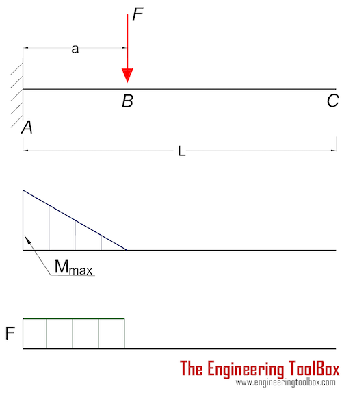
Cantilever Beam - Single Load

Maximum Reaction Force
at the fixed end can be expressed as:
RA = F (2a)
where
RA = reaction force in A (N, lb)
F = single acting force in B (N, lb)
Maximum Moment
at the fixed end can be expressed as
Mmax = MA
= - F a (2b)
where
MA = maximum moment in A (N.m, N.mm, lb.in)
a = length between A and B (m, mm, in)
Maximum Deflection
at the end of the cantilever beam can be expressed as
δC = (F a3 / (3 E I)) (1 + 3 b / 2 a) (2c)
where
δC = maximum deflection in C (m, mm, in)
E = modulus of elasticity (N/m2 (Pa), N/mm2, lb/in2 (psi))
I = moment of Inertia (m4, mm4, in4)
b = length between B and C (m, mm, in)
Maximum Deflection
at the action of the single force can be expressed as
δB = F a3 / (3 E I) (2d)
where
δB = maximum deflection in B (m, mm, in)
Maximum Stress
The maximum stress can be calculated by combining 1d and 2b to
σmax = ymax F a / I (2e)
Cantilever Beam - Single Load Calculator
A generic calculator - be consistent and use metric values based on m or mm, or imperial values based on inches. Default typical values are in metric mm.
Cantilever Beam - Uniform Distributed Load

Maximum Reaction
at the fixed end can be expressed as:
RA = q L (3a)
where
RA = reaction force in A (N, lb)
q = uniform distributed load (N/m, N/mm, lb/in)
L = length of cantilever beam (m, mm, in)
Maximum Moment
at the fixed end can be expressed as
MA = - q L2 / 2 (3b)
Maximum Deflection
at the end can be expressed as
δB = q L4 / (8 E I) (3c)
where
δB = maximum deflection in B (m, mm, in)
Cantilever Beam - Uniform Load Calculator
A generic calculator - use metric values based on m or mm, or imperial values based on inches. Default typical values are in metric mm.
More than One Point Load and/or Uniform Load acting on a Cantilever Beam
If more than one point load and/or uniform load are acting on a cantilever beam - the resulting maximum moment at the fixed end A and the resulting maximum deflection at end B can be calculated by summarizing the maximum moment in A and maximum deflection in B for each point and/or uniform load.
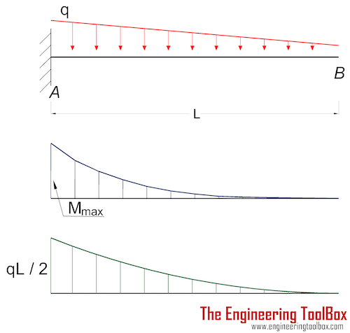
Cantilever Beam - Declining Distributed Load

Maximum Reaction Force
at the fixed end can be expressed as:
RA = q L / 2 (4a)
where
RA = reaction force in A (N, lb)
q = declining distributed load - max value at A - zero at B (N/m, lb/ft)
Maximum Moment
at the fixed end can be expressed as
Mmax = MA
= - q L2 / 6 (4b)
where
MA = maximum moment in A (N.m, N.mm, lb.in)
L = length of beam (m, mm, in)
Maximum Deflection
at the end of the cantilever beam can be expressed as
δB = q L4 / (30 E I) (4c)
where
δB = maximum deflection in B (m, mm, in)
E = modulus of elasticity (N/m2 (Pa), N/mm2, lb/in2 (psi))
I = moment of Inertia (m4, mm4, in4)
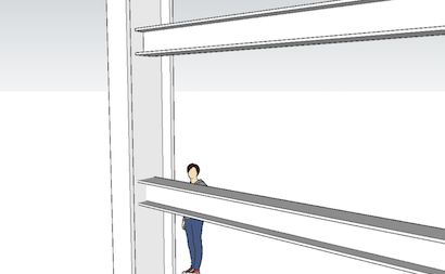
Insert beams to your Sketchup model with the Engineering ToolBox Sketchup Extension
Related Topics
-
Beams and Columns
Deflection and stress in beams and columns, moment of inertia, section modulus and technical information.
Related Documents
-
Area Moment of Inertia - Typical Cross Sections I
Typical cross sections and their Area Moment of Inertia. -
Beam Loads - Support Force Calculator
Calculate beam load and supporting forces. -
Beams - Fixed at Both Ends - Continuous and Point Loads
Stress, deflections and supporting loads. -
Beams - Fixed at One End and Supported at the Other - Continuous and Point Loads
Supporting loads, moments and deflections. -
Beams - Supported at Both Ends - Continuous and Point Loads
Supporting loads, stress and deflections. -
Center Mass
Calculate position of center mass. -
Continuous Beams - Moment and Reaction Support Forces
Moments and reaction support forces with distributed or point loads. -
Drawbridge - Force and Moment vs. Elevation
Calculate the acting forces and moments when elevating drawbridges or beams. -
HE-B Steel Beams
Properties of HE-B profiled steel beams. -
Levers
Use levers to magnify forces. -
Mass Moment of Inertia
The Mass Moment of Inertia vs. mass of object, it's shape and relative point of rotation - the Radius of Gyration. -
Square Hollow Structural Sections - HSS
Weight, cross sectional area, moments of inertia - Imperial units -
Steel Angles - Equal Legs
Dimensions and static parameters of steel angles with equal legs - metric units. -
Steel Angles - Unequal Legs
Dimensions and static parameters of steel angles with unequal legs - imperial units. -
Steel Angles - Unequal Legs
Dimensions and static parameters of steel angles with unequal legs - metric units. -
Stiffness
Stiffness is resistance to deflection. -
Three-Hinged Arches - Continuous and Point Loads
Support reactions and bending moments. -
Trusses
Common types of trusses. -
Weight of Beams - Stress and Strain
Stress and deformation of vertical beams due to own weight. -
Wood Headers - Max. Supported Weight
Weight supported by a double or triple wood headers. -
Young's Modulus, Tensile Strength and Yield Strength Values for some Materials
Young's Modulus (or Tensile Modulus alt. Modulus of Elasticity) and Ultimate Tensile Strength and Yield Strength for materials like steel, glass, wood and many more.


