Moody Diagram
Calculate fluid flow friction coefficients from a Moody diagram.
There are two definitions of the friction factor
- SI based
- Imperial based
The SI based friction factor is four times larger than the Imperial based friction factor.
SI based Moody Diagram
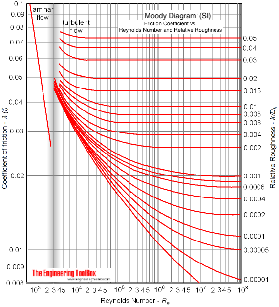
The Moody friction factor - λ (or f) - is used in the Darcy-Weisbach major loss equation. The coefficient can be estimated with the diagram below:

If the flow is transient - 2300 < Re < 4000 - the flow varies between laminar and turbulent flow and the friction coefiicient is not possible to determine. The friction factor can usually be interpolated between the laminar value at Re = 2300 and the turbulent value at Re = 4000 .
Example - SI based Friction Factor
For a PVC pipe with absolute roughness k = 0.0015×10⁻³ (m) , hydraulic diameter d h = 0.01 (m) and Reynolds number Re = 10 7 - the relative rougness can be calculated as
r = k / dh
= (0.0015×10⁻³ m) / (0.01 m)
= 0.00015
From the diagram above, with the relative rougness and the Reynolds number - the friction factor can be estimated to aprox. 0.013 .


